A sphere that makes electrons oscillate
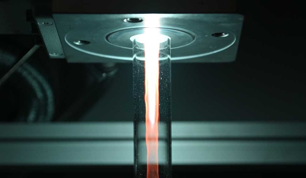
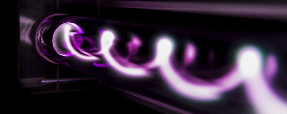
Plasmas play a vital role in many industrial applications. The energetically excited gases can be used, for example, to deposit coatings on surfaces, such as scratch-resistant protective layers on plastic spectacle lenses, or high-precision optical filters on quartz glass. In the process, the plasma is used to bombard the coatings that grow on the substrate by vapour deposition with ions, thus effectively hammering them into place.
But such processes must meet many requirements. For example, they must take place at low temperatures to prevent damage to the coated surfaces. “In modern production processes, more and more emphasis is also being placed on precision,” stresses Professor Ralf Peter Brinkmann, who holds the Chair for Theoretical Electrical Engineering at RUB. All resulting products must be exactly the same, and the coating must be defect-free. To achieve this level of precision, it is necessary to constantly monitor the plasma. The electron density is particularly important in coating processes. If it were to fluctuate too much, this would negatively affect the quality of the finished coating. “Ideally, the electron density should be constantly measured and automatically readjusted if necessary, so that no human has to interfere in the process,” explains Brinkmann.
Small, reliable, maintenance-free
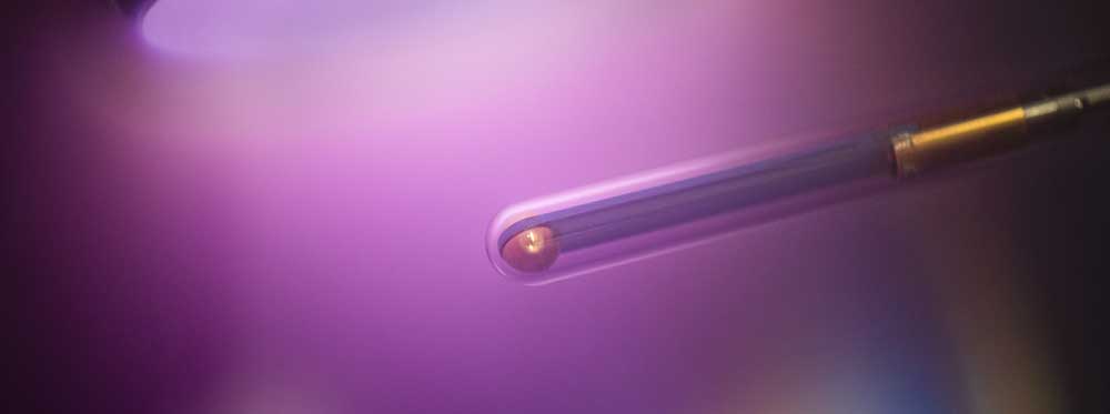
A measuring instrument that can do all this has to meet a variety of requirements: It should be as small as possible, reliable, maintenance-free, and it must neither interfere with the coating process nor be damaged in the plasma. Experts refer to this as “process-compatible plasma diagnostics”.
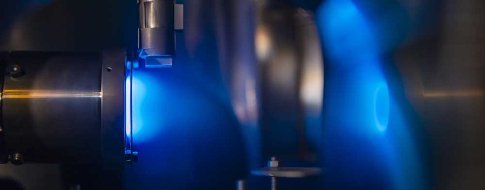
Researchers have been pursuing one idea for a long time: The electrons, which move freely in the plasma, can be made to oscillate by applying a small external voltage. If the right frequency is hit, a detectable resonance occurs. Since the resonance frequency depends on the electron density, this can then be theoretically calculated.
Picture this like driving an old car.
– Ralf Peter Brinkmann
However, earlier attempts to put this idea into practice encountered some difficulties. A Japanese research group, for example, proposed a very simple construction: The team used a coaxial cable, similar to an analogue antenna cable, allowed the inner conductor to protrude a little, and inserted the end of the cable into the plasma. If a voltage was applied, resonances of the plasma could be measured. However, resonances of equal value occurred at several different frequencies – a veritable zoo. “The problem was: which one should be used for diagnostics,” explains Ralf Peter Brinkmann.
Analyses by the Bochum-based researchers provided an answer to the question of where the different resonances came from: As simple as the design of the measuring equipment was, different oscillations with different resonance frequencies arose at different sections of the apparatus. “Picture this like driving an old car,” as Ralf Peter Brinkmann illustrates the principle. “At a certain speed, the exhaust rattles, at another, it’s the wing mirror.”
The more symmetrical, the better
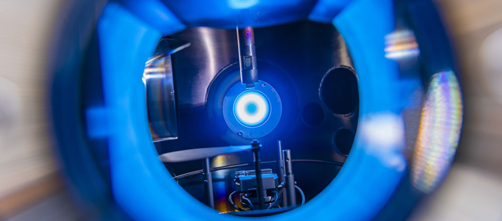
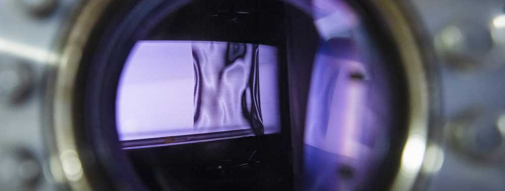
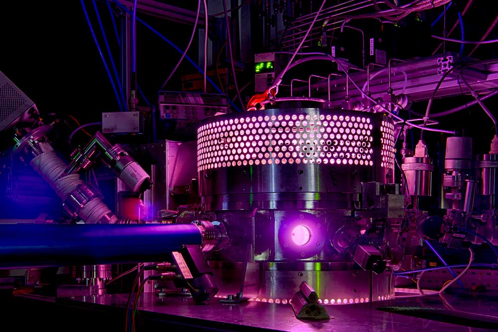
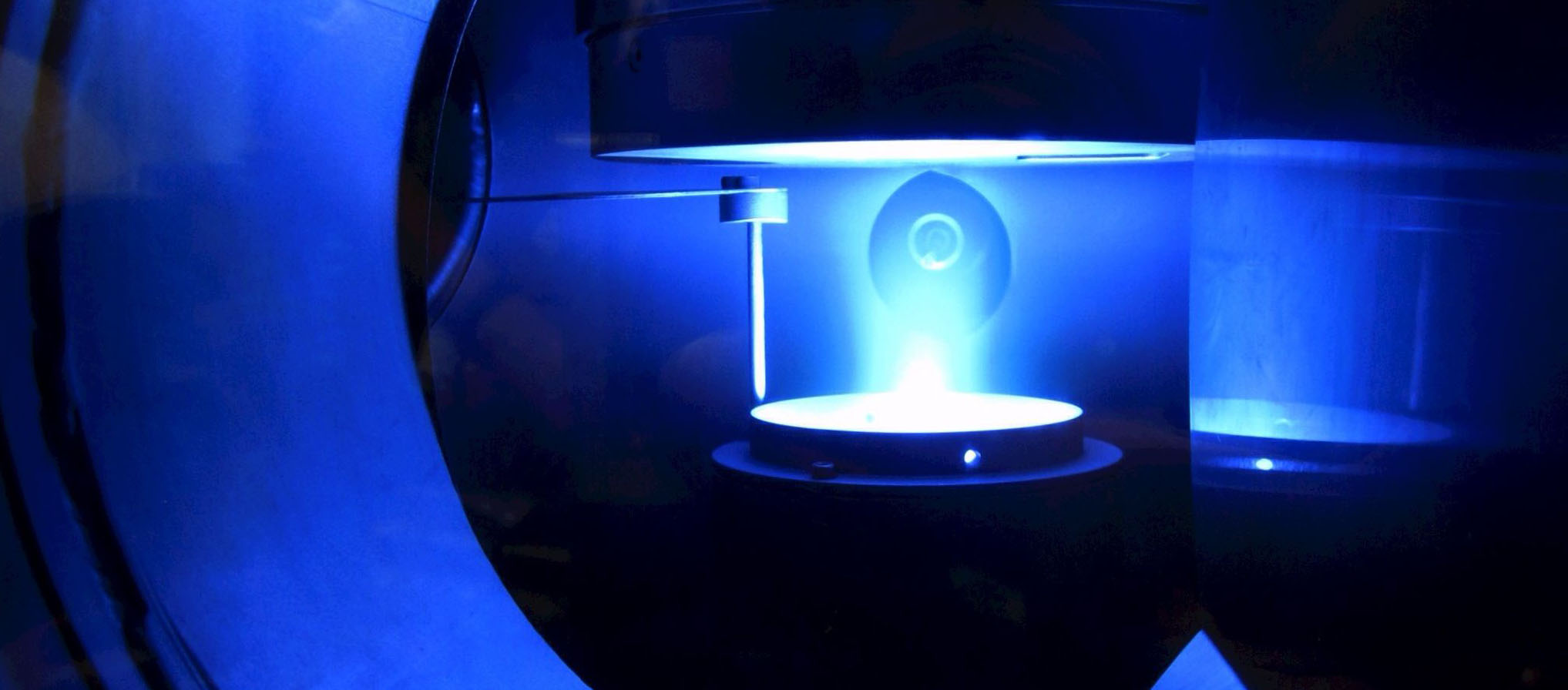
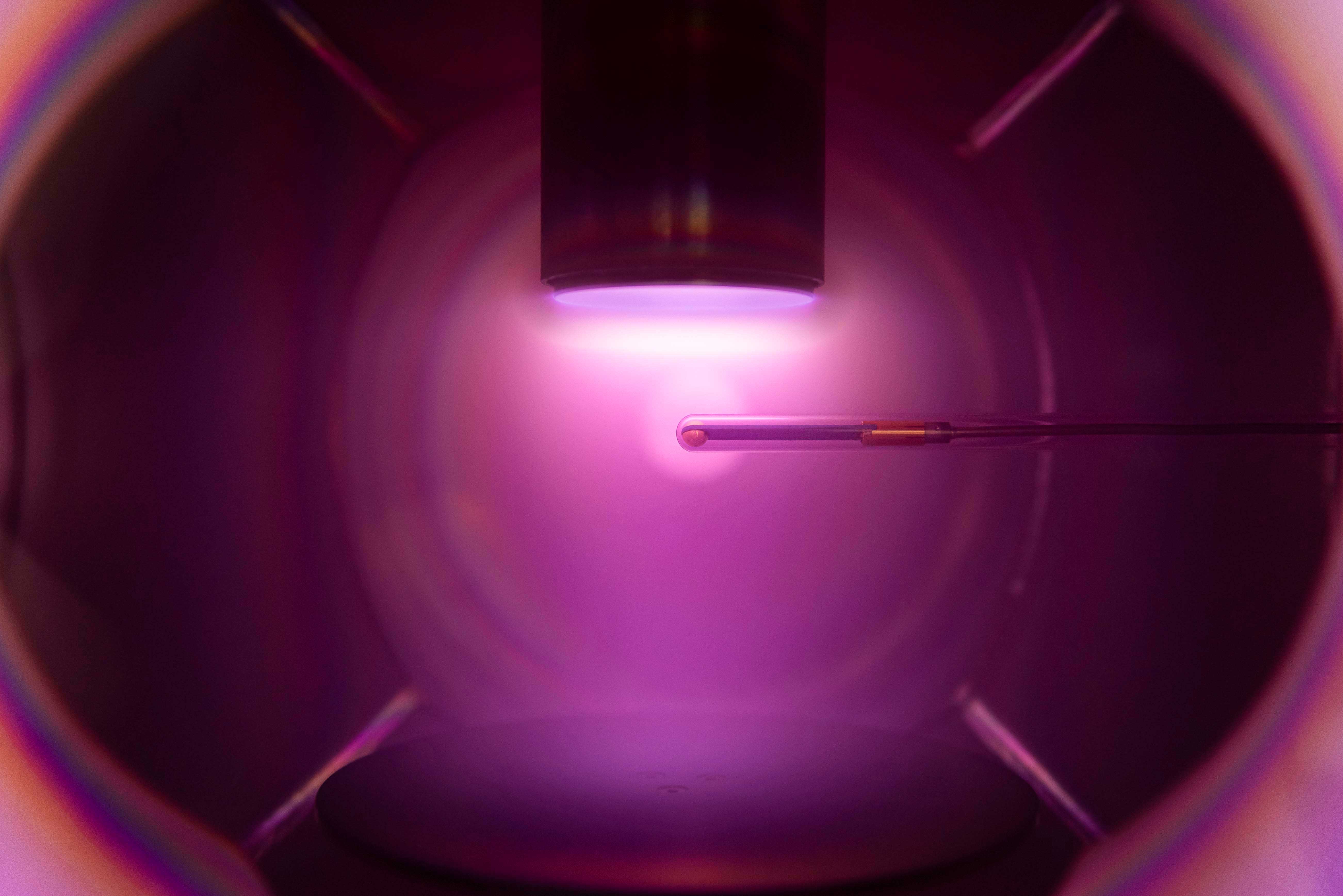
To remedy the situation, the team devised a concept that aimed for the simplest possible oscillations. Their aim was: the more symmetrical, the better. “The spherical shape is the simplest configuration imaginable,” says Brinkmann. “A floating marble would’ve been our first choice.” However, it was not quite that simple, of course. Electricity always needs a forward and a return conductor. Accordingly, two metallic hemispheres were chosen. The construction is rotationally and mirror-symmetrical, both electrodes are the same size. “Here, too, we measure resonances at different frequencies,” explains Ralf Peter Brinkmann. “But they can be clearly sorted. The strongest resonance is the dipole resonance; the other, weaker ones, represent the overtones to this keynote, so to speak.” The name “multipole resonance probe” (MRP) was derived from the mathematical method of “multipole analysis” used for this purpose.
The reason why researchers opt for the MRP is that the relationship between plasma density and resonance frequency is given by a simple mathematical formula. The plasma density is the only unknown in this equation. Once the equation is solved, it can be calculated from the measured values. “This means that it is not necessary to calibrate the measuring probe before use, i.e. to compare it with other measured values,” elaborates Ralf Peter Brinkmann.
Plasma was kept consistent through constant monitoring
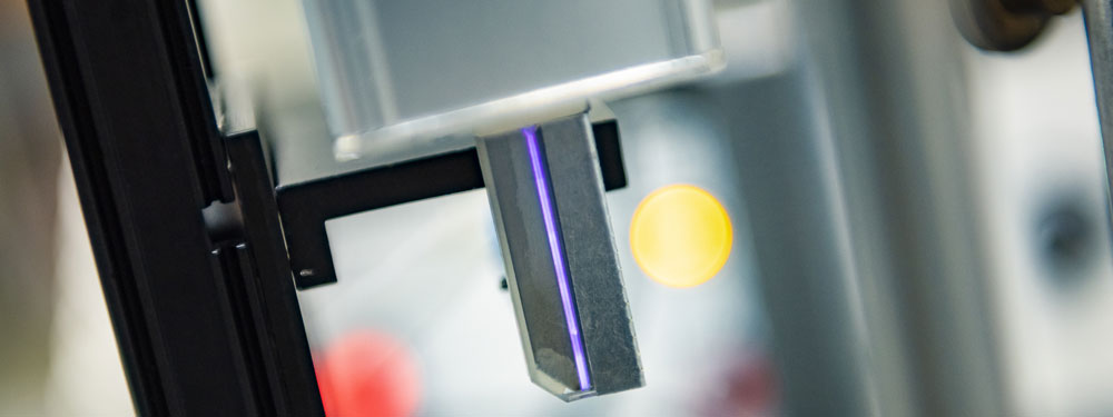
So much for the underlying theory. For practical implementation, the researchers teamed up with three other chairs at the faculty. Professor Ilona Rolfes’ High Frequency Engineering Institute carried out a high-frequency optimisation of the entire system consisting of probe head and holder. For example, it was possible to make the holder practically invisible to the plasma. Professor Thomas Musch’s Institute of Electronic Circuits designed control electronics based on radar technology. And finally, Professor Peter Awakowicz’ Institute for Electrical Engineering and Plasma Technology tested the finished probe in a number of plasma processes.
The Federal Ministry of Education and Research funded the joint projects Pluto and Pluto plus to develop the MRP to the point where it could be used in practice. This also provided the opportunity to test the probe with industrial partners. And it turned out that if the electron density in the plasma was kept consistent through constant monitoring by means of MRP and automatic adjustment of the control, the fluctuations in the process results were significantly reduced.
Today, a spin-off is about to get off the ground.
adapted from Meike Drießen (RUB)